


A Modbus energy meter correctly responds to tests performed on the bench but begins timing out after being installed on a shared RS485 network. More devices on the network increases the problem. The gateway retains either an Ethernet or cellular connection. Measurements sometimes arrive late or not at all.
Replacing the gateway will not resolve the issue. There are other possibilities including reflections from unterminated cable branches, conflicts due to slave addresses being assigned more than once, excessive polling, and serial timing issues.
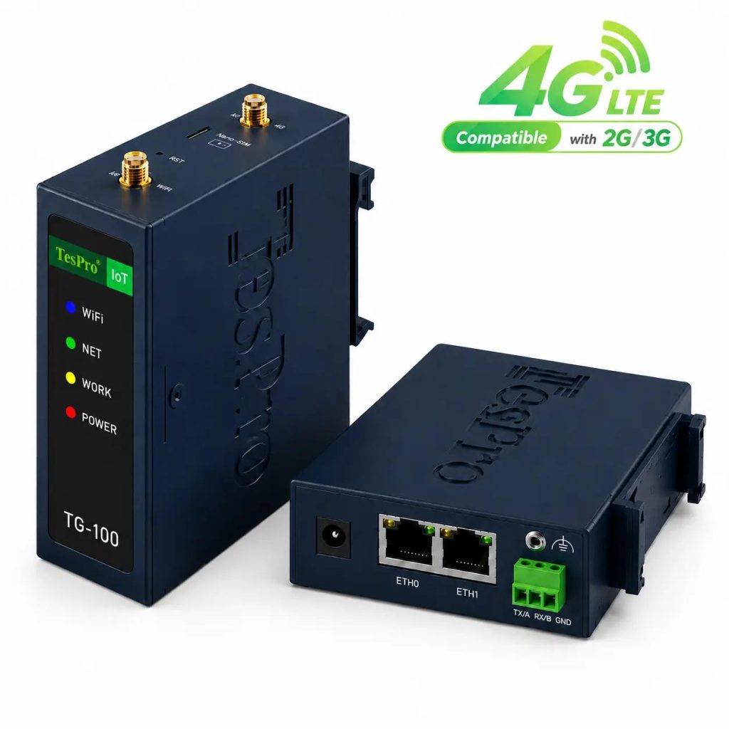
When evaluating the communications requirements of our customers in the field, at Tespro, we take into account these types of field-level constraints. As an Industrial Gateway Manufacturer, we provide various Models of RS485-enabled gateways that support conversion of Modbus RTU/TCP as well as industrial data acquisition and communication over Ethernet or cellular networks.
1. RS485 Communication: Check the Physical Layer First
RS485 provides differential electrical signaling; Modbus RTU defines the message structure exchanged across that connection. A gateway can support both standards and still fail to communicate reliably with an incorrectly wired network.
In a conventional two-wire, half-duplex installation, connected devices share one communication pair. The Modbus master initiates transactions, and addressed slave devices respond sequentially.
Reliable RS485 communication depends on the following factors:
Termination placement: Install termination resistors matching the cable's characteristic impedance at both ends of the main RS485 bus. Avoid unnecessary termination at intermediate devices.
Branch lengths: Keep device stubs as short as possible. Long branches can cause impedance discontinuities and signal reflections.
Grounding and shielding: Use appropriate grounding and shielding practices to minimize ground potential differences, common-mode interference, and communication errors.
A/B polarity: Verify the A/B terminal definitions in each device's documentation, as labeling conventions may differ between manufacturers.
Serial parameters: Ensure that all connected devices use matching baud rates, data bits, parity, and stop-bit settings.
Modbus RTU frame timing: Verify the required silent intervals between frames and characters. At baud rates up to 19,200 bps, Modbus RTU specifies at least 3.5 character times between frames and uses a 1.5-character-time threshold for detecting invalid gaps within a frame. For higher baud rates, the specification recommends fixed timing values.
Modbus RTU uses silent intervals to define frame boundaries. A minimum silent interval of 3.5 character times is typically required between consecutive frames. Within a frame, a silent gap exceeding approximately 1.5 character times may cause the receiver to treat the frame as incomplete or invalid. The exact timing requirements depend on the baud rate and implementation, with fixed timing values recommended for baud rates above 19,200 bps.
When serial communication errors occur, the frame and the Cyclic Redundancy Check (CRC) may be evaluated.
2. Modbus RTU to TCP: Select the Best Conversion Method
There are several Modbus (RS485) to Ethernet gateways on the market. Our tespro gateways support serial, Modbus RTU-to-TCP, and MQTT communications. The preferred system architecture will dictate the selected communications method.
| Communication mode | Data handling | Engineering consideration |
| Transparent TCP/UDP | Forwards serial data without interpreting Modbus registers | The remote application must manage framing and device requests |
| Modbus RTU-to-TCP | Converts TCP requests into serial Modbus transactions | Concurrent TCP requests must be scheduled on the shared serial bus |
| Modbus polling with MQTT | Collects selected register values for upstream publication | Requires register mapping, polling configuration, and payload definition |
Modbus TCP uses an MBAP header containing transaction information and a Unit Identifier. Modbus RTU instead uses a serial address field and CRC. A protocol gateway must translate these elements without changing the intended function code or register request.
A further limitation appears when multiple SCADA clients access the same RS485 segment. Ethernet can carry concurrent requests, but the serial bus cannot execute overlapping Modbus RTU transactions.
The gateway must queue or otherwise arbitrate requests. Buyers should investigate how the selected firmware handles concurrent clients and timeouts and pending transactions.
3. Register Mapping: Prevent Incorrect Values from Entering SCADA
Not all valid Modbus responses are correct.
In one instance, a meter reported an energy value using a 32-bit floating point number and stored it in a pair of 16-bit registers. If the gateway, in transit, serialized the registers in the wrong order, the reported value would be meaningless, and the Modbus frame would still validate CRC.
Prior to configuration, the following should be recorded:
•Function codes. Used to define read operations e.g. function codes 03 and 04 for holding and input registers.
•Register addressing. E.g. resolve differences between human-readable IDs and zero-based addresses.
•Data formats. E.g. signed and unsigned integers, floating point, multi-registers etc.
•Byte and word ordering. E.g. ABCD, CDAB etc.
•Scaling factors. E.g. multipliers, engineering units etc.
Tespro's gateway supports multiple byte order and integer/floating point formats.
The gateway's functions facilitate integration with field devices, however they do not substitute a correct register map. Commissioning engineers should verify the values against an independently running Modbus client or the device display.
4. Polling Intervals: Calculate the Real RS485 Workload
A gigabit Ethernet interface does not increase the throughput of a downstream serial bus.
Each Modbus request and response has an associated processing and latency time. Timeouts and retries introduce further delays.
Networks with multiple meters or PLCs require the polling cycle to account for all scheduled transactions.
Total scan time = request transmission + device response time + response transmission + frame delays + retry overhead (summed across all the requests)
There are three ways to limit serial traffic:
- If support is present in the device, contiguous registers can be combined and read as a single request.
- Less critical parameters that do not affect operation can be polled less frequently.
- A disconnected slave can be configured for a bounded retry.
Larger request size do not guarantee better responses, and in some cases (eg. Modbus), reading an unsupported register can result in a communication exception.
The difference between the acquisition interval (time between sample and hold) and the reporting interval (time between sample and release) needs to be taken into account when trying to optimize polling. A gateway configured to publish every second cannot supply fresh measurements every second if its complete serial scan takes longer.
Polling reliability depends on field-device availability, RS485 wiring, configured timeouts and retries, and actual bus loading; validate the scan cycle on site.
5. Which Tespro Gateway Fits the RS485 Network?
The selection process should begin with the number of independent serial segments, not simply the fastest available upstream network.
Tespro provides several gateway configurations:
| Model | Serial configuration | Published connectivity | Selection consideration |
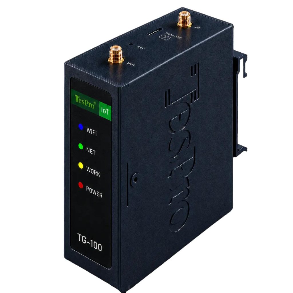
| TG-100 | 1×RS485 or 1×RS232, selectable | 4G, 100 Mbps Ethernet, Wi-Fi 4 | Single serial segment |
| TG-324 | 2×RS485 + 1×RS232 | 4G, Gigabit Ethernet, Wi-Fi 4/5 | Multiple serial networks |
| TG-325 | 2×RS485 + 1×RS232 | 4G/5G, Gigabit Ethernet, Wi-Fi 4/5 | Cellular installations requiring 5G options |
| TG-424 | 2×RS485 + 1×RS232 | 4G, Gigabit Ethernet, Wi-Fi 4/6 | Serial acquisition with higher local processing requirements |
Tespro offers 3 kV isolation for these serial interfaces. The isolation test conditions and protection requirements should be confirmed for the intended installation. Isolation does not eliminate the need for appropriate grounding or external surge protection.
Two RS485 ports can also simplify installations involving physically separate equipment networks. Whether each port can operate with independent serial parameters should be verified against the selected firmware configuration.
6. Acceptance Testing Before Industrial Gateway Procurement
A successful demonstration with one meter and a short cable is insufficient evidence for a multi-device installation.
We recommend testing representative equipment under expected operating conditions.
Communication Validation
• Verify complete RS485 network with all planned device addresses.
• Compared decoded register values with known reference readings.
• Disconnected a slave and verified timeout and recovery handling.
• Test required polling cycle with normal and failed device conditions.
Gateway and Application Validation
• Test handling and exception responses of Modbus TCP Unit Identifier.
• Verify behavior with case of multiple upstream client requests, if applicable.
• Test reconnection behavior after interrupting the Ethernet or cellular uplink.
• Confirm which measurements are available after communication disruptions.
• Restrict Modbus write access where remote parameter changes are not needed.
Modbus TCP does not authenticate application requests. Thus, remote access to the application is not secure. Therefore, it is necessary to adequately isolate the network, implement the correct firewall rules, and configure access controls.
In addition, prior to a bulk order, buyers should verify firmware versions, check the capacity of registers supported, define the limits of the TCP client, and understand the data buffering and serial configuration options.
Discuss RS485 Integration with Tespro
Tespro can assist with the selection of the most appropriate industrial gateway and OEM/ODM requirements for a monitoring system based on Modbus. Depending on your polling requirements and the architecture of your system, contact Tespro's engineering team for an evaluation.
Explore Tespro Industrial Gateway Solutions
FAQs
Q1. What RS485 interfaces do Tespro industrial gateways provide?
Tespro's TG-100 offers one selectable RS485 or RS232 interface. The TG-324, TG-325, and TG-424 provide two RS485 ports and one RS232 port.
Q2. Do Tespro industrial gateways support Modbus RTU and Modbus TCP?
Yes. Tespro gateways support Modbus RTU and Modbus TCP for connecting serial field devices with industrial Ethernet networks.
Q3. Can Tespro gateways convert Modbus RTU to Modbus TCP?
Yes. The TG-325 supports Modbus RTU-to-TCP conversion, allowing RS485 devices to communicate with compatible Ethernet-based applications.
Q4. Can Tespro gateways transmit Modbus data through MQTT?
Yes. The TG-325 supports MQTT communication for transmitting collected industrial data to compatible IoT platforms and cloud applications.
Q5. How does Tespro support Modbus register mapping?
The TG-325 supports multiple integer and floating-point formats, including configurable byte-order conversion for accurate register interpretation.


